All types of commercial microphones (condenser, dynamic and ribbon) work on the same basic principle – the displacement of a diaphragm (or with ribbon microphones, a long, narrow ribbon) by a sound wave is made to produce a corresponding voltage swing. Moving coil (dynamic) and ribbon microphones are electromagnetic devices and in their simplest forms can produce useable audio signals without any additional electronic help.
With a condenser microphone, the microphone capsule consists of a very thin, flexible diaphragm which is spaced a minute distance in front of a rigid, insulated electrode referred to as a backplate. This diaphragm and backplate form the two plates of a capacitor, which, in the absence of a sound wave, will have a very small but definite capacitance. However, when a sound wave displaces the diaphragm, the capacitance will either be increased above or reduced below the “resting” value; depending upon whether the sound wave pushes the diaphragm toward the backplate or causes it to bow out away from the backplate.
Although this variable capacitance will not generate an audio signal on its own, it can be connected into a suitable electrical circuit so that the capacitance change will produce a corresponding voltage change in the external circuit, as illustrated in the figure below:
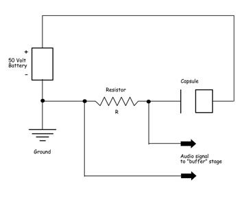
In the figure, the 50 volt battery’s positive terminal connects to the “backplate” of the microphone capsule and the negative terminal is grounded. The capsule’s diaphragm is also grounded through the resistor R. In this case, the capacitance will charge in a time determined by the RC time constant (T in seconds = C in FARADS multiplied by R in OHMS) and once the capacitor is charged, the backplate would be 50 volts above ground and the diaphragm would be at ground potential. Any change in the capacitance, though, will result in a voltage swing across R, which may serve as both the OUTPUT load for the capsule and as the INPUT load on a following “buffer” amplifier.
With practical capacitor microphone capsules, the capacitance is very small and R must be a resistor with a resistance of several hundred million ohms in order for the output voltage to correspond to the diaphragm displacement throughout the audio range. Also, the microphone capsule and R must have a “buffer” amplifier within an inch of them, to avoid excessive signal loss and noise pickup and this “buffer” stage must have an extremely high input impedance; a vacuum tube or a FET must be used on account of the impedance of the signal source.
In commercial capacitor microphones, the battery in the figure is eliminated and the voltage is taken from the DC supply voltage that is sent down the cable to operate the capsule and the buffer amplifier – “phantom” power in the case of transistorized microphones or voltages furnished by a dedicated power supply, in the case of most tube microphone designs.